Building the Banshee: Part 2
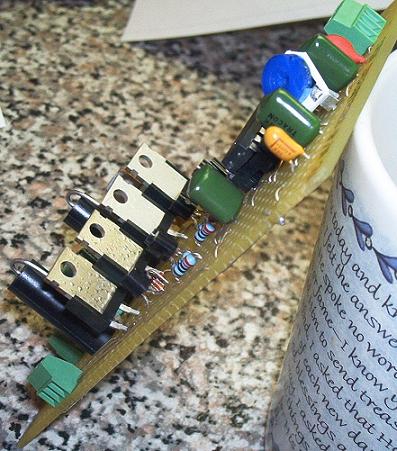
When I started testing the boards, I could get them to run a motor only for a couple of minutes before one or two of the FETs (out of four on each board) would over heat and fail. On one board two FETs (note: FET stands for Field Effect Transistor) got so hot before I managed to kill the power to them that the solder on the back started to melt and bead up.
You can see the discoloration and beaded solder on the two FETs that fried:
After some exchanges and much troubleshooting on his support forum, I ended up sending Mr. Kleinbauer one of my boards to see if he could find the trouble. After replacing a couple of fried FETs, he tested the board for several hours and was unable to find a problem. So, he mailed the board back to me so I could try running it. I did and promptly fried another FET.
After this, Mr. Kleinbauer suggested that the problem might in the motors themselves. Of course, I knew that there was nothing wrong with my motors as I had tested them with a multi-meter several times and couldn’t find a problem. Even so I headed back out to the garage, cheap Harbor Freight multi-meter in hand, to test them again. While metering out the motor I had been hooking up to the boards to test them with I had an idea. First I tested with the meter while the cable was just laying on the bench where it does when it’s not hooked up to anything, and found no problems, then I moved the cable to where it would lay when hook up to a board for testing, and promptly found a couple of shorts. Upon further inspection, I found that on almost all of my motor cables, the electrical tape I had wrapped around the (rather poor) solder joints where the cables were spliced to the leads on the motors had slid around (or fallen off completely) and many of the motor wires were shorting together and causing the FETs to burn up. It turns out that, as usual, Mr. Kleinbauer was right, it was the motors at fault.
It is a great testament to the design of the Banshee that (even when built by someone like me) when it has 24V at 8.5Amps shorted through it it only manages to lose one or two components, whereas some other stepper controllers would’ve been completely destroyed.
After completely remaking the motor cables (I used shrink tubing to cover the splices this time) I found that one of my motors would short out internally once it warmed up. Since I only had four motors and needed all four to run my machine I ended up buying all new, 127 oz/in. NEMA 23 motors from HobbyCNC.com.
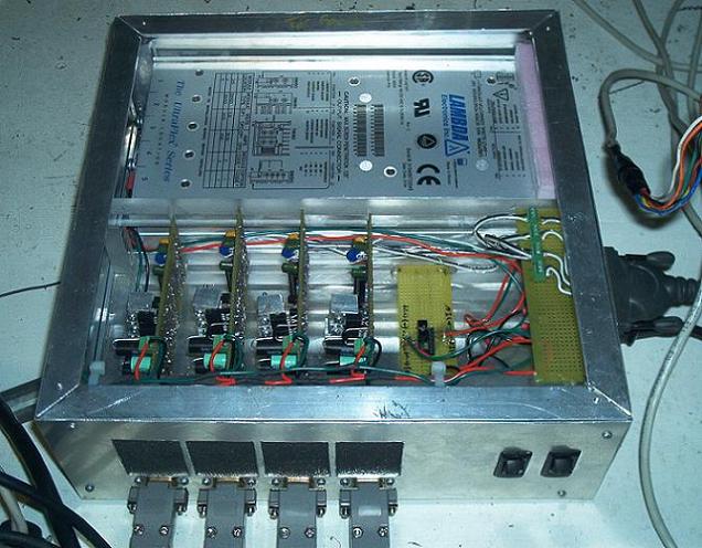
With the new motors, the Banshees worked perfectly. All I needed now was to build an enclosure and mount the motor on the machine. I built the enclosure with a frame of 1/8″ by 3/4″ aluminum angle welded together with my 110V Harbor Freight MIG welder and covered it with some 0.030″ aluminum sheet.
The homebuilt enclosure:
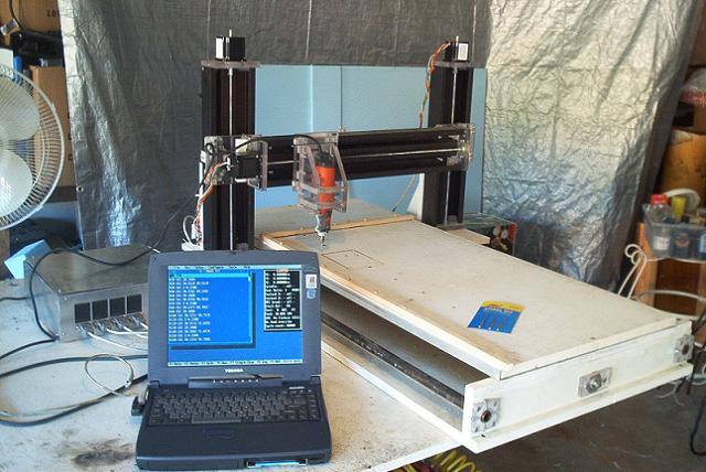
Motors mounted and machine ready to run (controller is at far right):
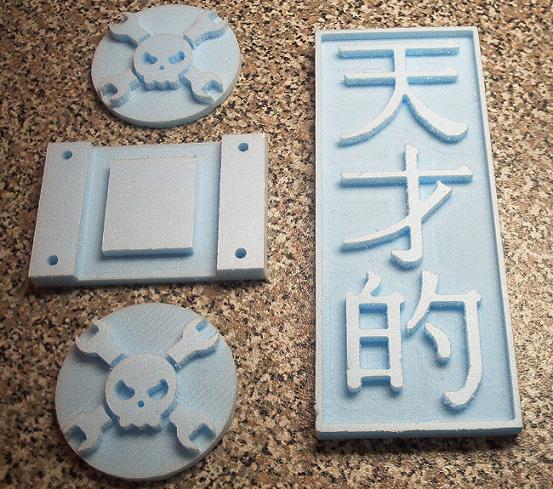
Here’s the products of the first few runs of the Banshee powered Pheonix Redux (milled out of 1/2″ insulation foam at 30 IPM with a 1/8″ end mill, the round things are about 4″ in diameter):
I would Highly recommend the Banshee if you are looking for a controller for anyone who has or is building a CNC machine. I prefer plans to kits (or ready-built). With plans you buy them once and can build the item as many times as you want and even modify it if you desire. With Kits, you can only build them once and, if you want to build another, you have to buy the kit again. It’s also a lot harder to modify/customize a kit.